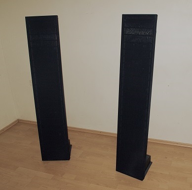
This model was called "300" because of its width. No surprises for people who know metric system here : it's 300 mm. Building those speakers has started back in 2008. It was completed only 5 years later. That's including three years of rough treatment shelved at a garage. Panels barely survived falls from heavy objects and needed some repairs to be back in service. Wires have been severely bent in a couple of places but have not detached from cross bars. Insulation was intact. The rough time proved construction materials were chosen right.
Those were : Aluminum(Frame), rigid PVC(spacers) and laminated plywood(cross bars). Combining them into a speaker turned out being a patience-training course. Rules like "If something can go wrong - it will" have been verified many times with a high degree of confidence. The material choices were driven by many factors. Some of those are discussed below.
Those were : Aluminum(Frame), rigid PVC(spacers) and laminated plywood(cross bars). Combining them into a speaker turned out being a patience-training course. Rules like "If something can go wrong - it will" have been verified many times with a high degree of confidence. The material choices were driven by many factors. Some of those are discussed below.
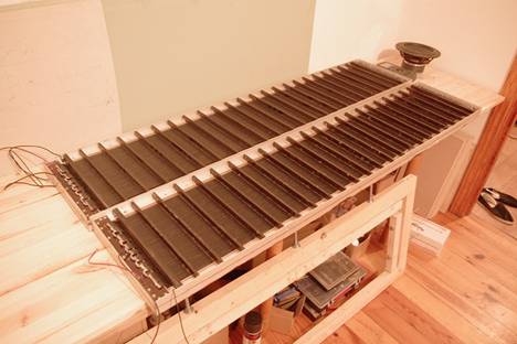
Aluminum frame
Advantages : good strength to volume ratio; very high degree of precision; possibility to do complete rebuilds(by ripping of plastic spacers).
Disadvantages : mainly a lot of work involved(each cross bar was fixed via screws). Special care needed to insulate frame from high voltages.
Laminated plywood cross bars
Advantages : Mechanically strong, simple to work with.
Disadvantages : Not a perfect insulator. Dimensions change somewhat depending on humidity.
Rigid PVC plastic for spacers.
While at first glance it looks like any plastic could be used, some are better than others. For example, various types of polystyrene or poly(methyl-acrylate, commonly called Plexiglass) tend to crack over time under persistent load. Polystyrene was tested and cracking around bolts was observed after a couple years of storage. Rigid PVC was chosen because of it’s somewhat higher flexibility.
PVC insulated copper wire(H05)
Solid core has been chosen. This type was cheap and available and did not arc yet, proving it's usability in a wire ESL. Core area is 0.5mm^2. Insulation thickness 0.6mm.
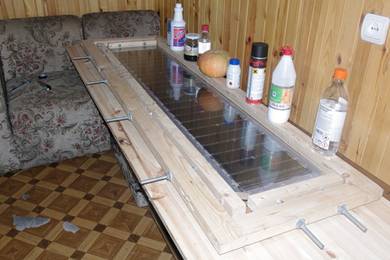
Diaphragm material
Experiments with various materials were carried out. In the final design Mylar C was used having thickness of 2 microns. It was stretched to approx. 0.8% elongation, mostly in the direction of width. It is additionally supported by a single row of silicone dots in the center of the speaker. The construction of frame for stretching film is relatively straightforward. Elongation of membrane was accounted for by carefully measuring several dots marked by a permanent pen. Acceptable consistency was obtained between different trials. Variation of fundamental resonance was within +/-5%.
A lot of different glues were experimented with for bonding mylar to spacers. Epoxy was selected due to its gap filling properties, no need of air contact for curing process and reliability in general. It was applied via syringe. Weight of stretching frame was sufficient to squeeze epoxy into a extremely flat layer without any voids or bubbles. Having some bottles and especially vegetables laying around is a plus.
Damping of the diaphragm.
It has been observed that damping of the fundamental resonance is very important in a full range ESL. Otherwise the sound is rough.
Many experiments were performed. It included various types of felt, fabrics and so on. Some of requirements were observed :
a) Damping must not emit dust particles or hair under any circumstances. If dust is trapped between membrane and stator it produces buzzing noises and sound quality is degraded. What is the point of targeting sub – 0.2% of harmonic distortion if noise figures are far higher than this?
b) The material should not be too thick. Felt or similar substances caused subjective loss of transparency of the sound.
After many attempts silk screen damping mesh was selected as suggested by members from DIYaudio. Because the speaker is covered via black thin material the mesh has no influence to optics. Furthermore, it was applied on the back side only.
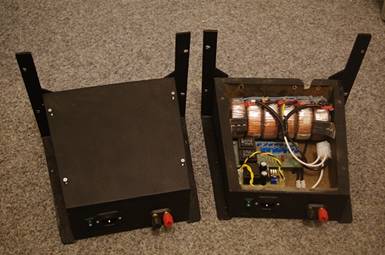
Choice of suitable transformers.
The intended frequency range (>=100Hz) and about 2mm d/s spacing called for a turns ratio of at least 1:100 and input voltage >= 20 Vrms@100Hz from transformer array. After some tests one particular type of power toroids were selected. They are rated at 230/11.5V. Manufactured by polish company Indel. Six of them have been combined into a final transformer array yielding effective turns ratio of about 1:115. The measured distortion of transformer array was neglible (<0.05% within audio range). Resonance due to parasitic capacitance and inductance is above 20 kHz. The disadvantage of using large core toroid transformers is high inter-winding capacitance, which leads to very low impedance at the end of audio spectrum. However the very low amplitude of audio signal at those frequencies do not trigger amplifier's protection circuits(an LM3886 chip amp is used).
The intended frequency range (>=100Hz) and about 2mm d/s spacing called for a turns ratio of at least 1:100 and input voltage >= 20 Vrms@100Hz from transformer array. After some tests one particular type of power toroids were selected. They are rated at 230/11.5V. Manufactured by polish company Indel. Six of them have been combined into a final transformer array yielding effective turns ratio of about 1:115. The measured distortion of transformer array was neglible (<0.05% within audio range). Resonance due to parasitic capacitance and inductance is above 20 kHz. The disadvantage of using large core toroid transformers is high inter-winding capacitance, which leads to very low impedance at the end of audio spectrum. However the very low amplitude of audio signal at those frequencies do not trigger amplifier's protection circuits(an LM3886 chip amp is used).
Electrical segmentation
Different resistor values for electrical segmentation were experimented with. Finally a 24 segment model was chosen. The reasons behind this were availability of 100KOhm/0.5w high voltage resistors and a belief that lower voltage gradients across membrane can result in better sounding speaker. A tool called ESL_Seg (available on downloads section) was used to simulate frequency response. Slightly rising response curve was selected to compensate for decreasing output off-axis above approx. 10 kHz. Simulated angles below are 0; 15; 30 degrees off axis.
Different resistor values for electrical segmentation were experimented with. Finally a 24 segment model was chosen. The reasons behind this were availability of 100KOhm/0.5w high voltage resistors and a belief that lower voltage gradients across membrane can result in better sounding speaker. A tool called ESL_Seg (available on downloads section) was used to simulate frequency response. Slightly rising response curve was selected to compensate for decreasing output off-axis above approx. 10 kHz. Simulated angles below are 0; 15; 30 degrees off axis.
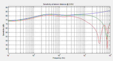
Frequency response Measurement
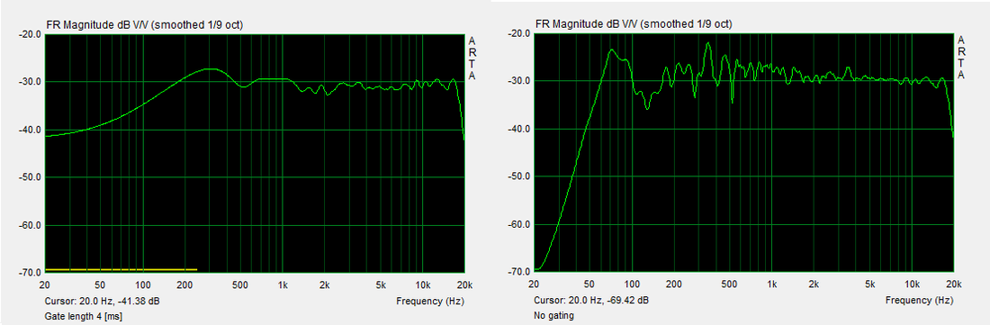
The frequency response represented below was taken in the listening room having dimensions approx 3(w)x4(l)x2.8(h)m. Room reflections make low frequency measurement nearly impossible as can be seen on the right diagram. Gated response(left) and non-gated(right) is displayed.
Harmonic distortion measurement,
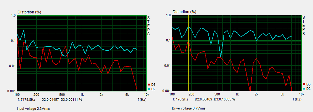
The measurement of total harmonic distortion is deemed tricky for large planar speakers by using near field measurement. Far-field measurement could be indicative, however reflections from walls makes such a measurement impossible in a typical room.
An interesting relationship between drive voltage and measured distortion levels was observed. In the case of low drive voltage of 2.3Vrms total harmonic distortion was generally very low, <0.1% from 150Hz and up. Things have changed to non-favorable side after voltage was increased to 8.7 Vrms.
This can be explained by the square relationship of distortion depending on signal level, as described in Baxandall's book "Loudspeaker and Headphone Handbook":
"It is also of interest to consider how the percentage distortion varies with the signal input level. The significant fact in this context is that the second-harmonic component of diaphragm voltage has a magnitude proportional to the square of the signal input voltage [....]
Thus , if Vsig is doubled E2f in Fig.3.19(b) is increased by a factor of four, giving four times as much fluctuation in diaphragm charge and consequently a fourthfold increase in the percentage distortion"
The bandwidth has been limited to 7 kHz. This is the maximum frequency @8.7Vrms to limit power dissipation in segmentation resistors.
The final result.
The speakers were initially designed to be paired with a subwoofer. However integration was a big problem, leading to fatiguing sound and uneven listening experience depending on listener's position. Sealed and dipole subwoofers have been tried. The conclusion was that a single subwoofer is not a good match for ESLs. Contrary to popular belief this does not have much to do with the weight of the diaphragm. The very high mechanical efficiency of electrostatic speaker makes high Q, long-decaying resonance at low frequency. This should be attenuated by using mechanical damping and/or electrical equalization.
However the situation is changed when room is taken into account. Often room dominates in frequency and impulse response over the speaker at low frequencies. Dipole radiation pattern of ESLs reduces reflections from walls side and ceiling. Furthermore, large surface of the speaker can be imagined as an array of woofers, creating an averaging effect. It has been known for a long time that multiple subwoofers improve bass response in typical rooms.
So the final decision was quite simple : run the ESL full range. That resulted in the most relaxing listening experience. There is an impression of soft, clean and accurate bass despite output level is dropping below 60 Hz.
Specifications.
External dimensions : 300x1500 mm
Radiating area : 0.34 m^2
Resonance frequency : 65Hz +/-5Hz
Frequency range : 55-20000 Hz
Sensitivity : approx. 80db/2.83V
Polarizing voltage : 4000V
Step-up ratio : 1:115
Maximum RMS input voltage : 20Vrms@80Hz/40Vrms@160Hz
D/S spacing : 2.1 mm.
External dimensions : 300x1500 mm
Radiating area : 0.34 m^2
Resonance frequency : 65Hz +/-5Hz
Frequency range : 55-20000 Hz
Sensitivity : approx. 80db/2.83V
Polarizing voltage : 4000V
Step-up ratio : 1:115
Maximum RMS input voltage : 20Vrms@80Hz/40Vrms@160Hz
D/S spacing : 2.1 mm.
